pfSense and the UniFi suite both support VLAN’s. It turns out to be very easy to configure them to work together with pfSense owning the VLAN definitions and addressing, and UniFi mapping those VLAN’s through to a WiFi AP. Here’s how:
Infrastructure
In my network I have:
- pfSense firewall / router built on a fanless mini-PC running a core i5 CPU, 8GB RAM and 6 NIC’s
- UniFi Controller running on a Raspberry Pi (part of my control node project)
- UniFi nano HD access point
I also have a UniFi US-24-250W switch, but this does not have a direct role to play in the VLAN and network config.
Note that when I first setup my router I wasn’t yet using VLAN’s and the 6 NIC’s were useful to be able to physically separate networks, but now it’s total overkill and two would be enough - one to the Internet uplink and one to the managed switch.
Procedure
We’ll go through the following steps:
- Define VLAN’s and subnets in pfSense
- Configure DHCP in pfSense
- Configure firewall rules in pfSense
- Map VLAN’s in UniFi controller
- Define WiFi SSID’s in UniFi controller
I’ll be defining two WiFi networks:
- purple - this is the network for trusted devices like our phones and laptops
- orange - this is for untrusted devices
The difference between these is that the purple network can access resources on the green (wired) network such as the Plex server. Orange generally just has access to the Internet.
Define VLAN’s and Subnets in pfSense
The target VLAN configuration is:
- Untagged - “GREEN” - for trusted computers and services on the wired LAN
- 20 - “PURPLE” - for trusted WiFi devices such as our phones and laptops
- 30 - “ORANGE” - for untrusted WiFi devices and such as guests phones and laptops
I already have the second port on the router (igb1) configured as GREEN with the subnet 10.80.2.0/24.
To create the VLAN’s we:
- Go to Interfaces > Assignments
- Click the VLANs tab
- Click the Add button to define the first VLAN which will be PURPLE
- Select the parent interface to be igb1 - the interface that the GREEN LAN network is on.
- Enter the tag “20”
- Enter the human-friendly description “PURPLE”
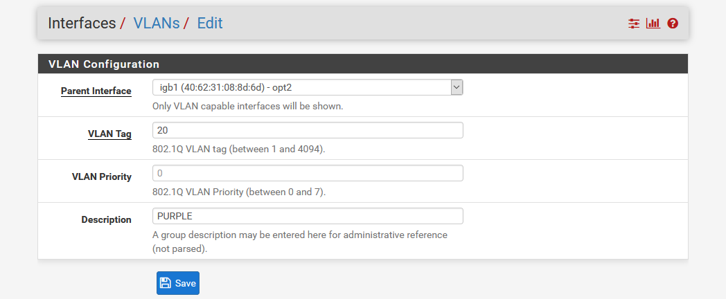
- Save
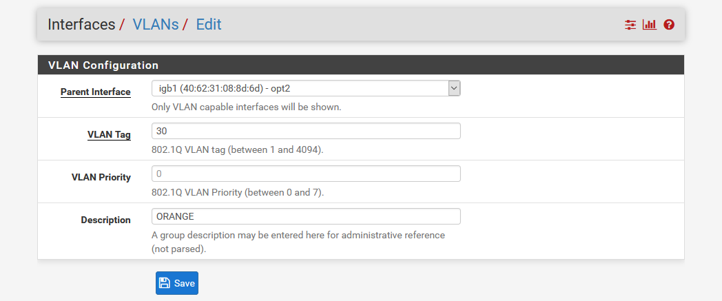
- Then repeat for the ORANGE network but with the tag “30” and the description “ORANGE”
- The VLAN’s are created:
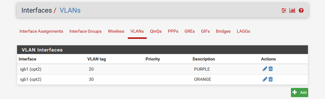
Note that since we have created the PURPLE and ORANGE VLAN’s under the parent interface that the GREEN LAN, they are all served through the same physical interface, meaning the single uplink from the pfSense router to the UniFi switch carries all three networks:
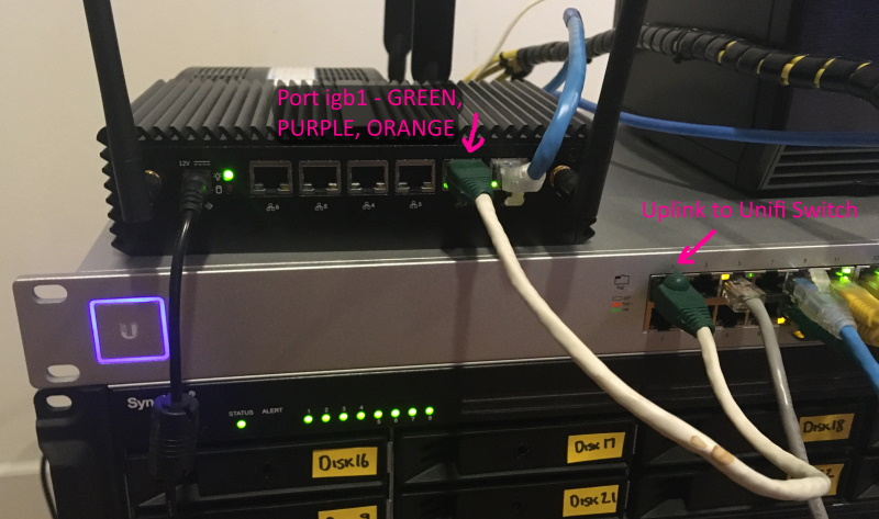
Later we’ll add config to the switch so that it can map the VLAN’s to the AP, but for now we need to define the networks for these VLAN’s:
- Click on the Interface Assignments tab
- In the bottom row in the table select the first VLAN “VLAN 20 on igb1 - opt2 (PURPLE)” and click Add
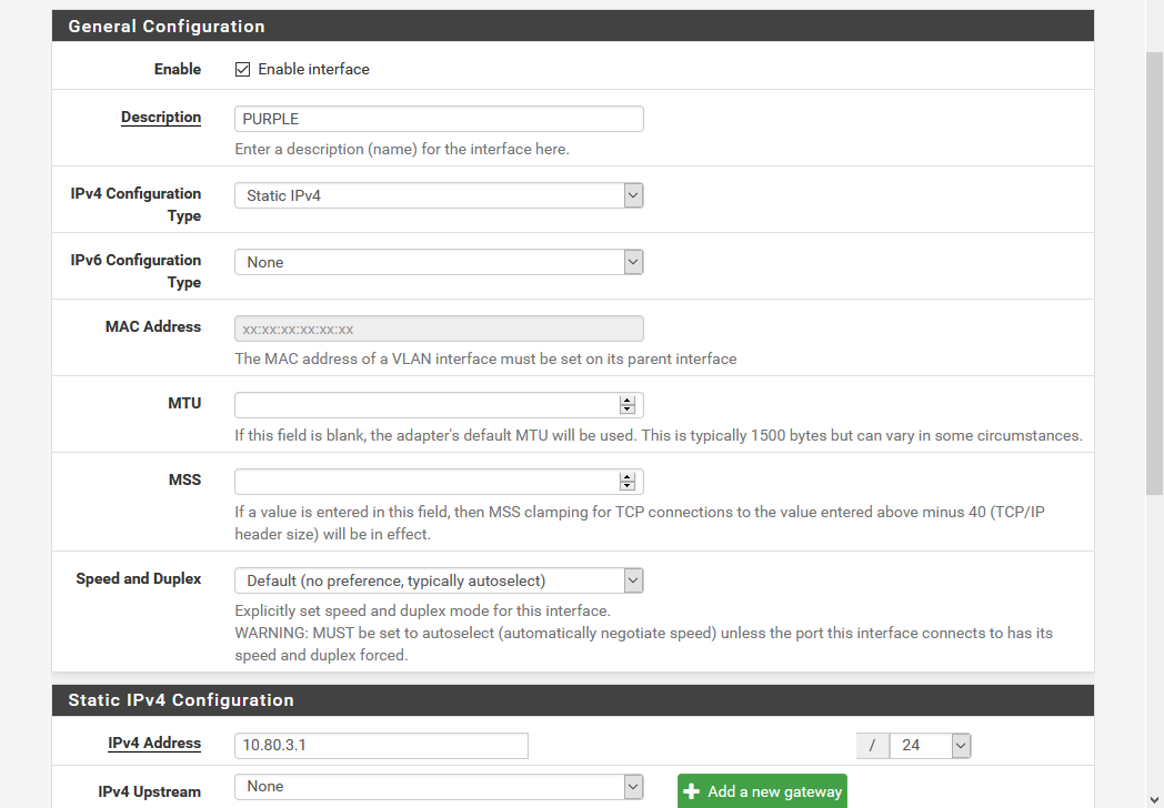
- Click the default Interface name that was generated for this interface to open it’s settings
- Check Enable Interface
- Change Description to “PURPLE” for clarity
- Under Static IPv4 Configuration enter the gateway address for this interface and specify the subnet size. For my PURPLE network I gave it the gateway 10.80.3.1 with the subnet being a /24.
- Now repeat for ORANGE with it’s own IP addressing.
Configure DHCP in pfSense
Now let’s configure the DHCP service for both of these new VLAN networks:
- Select Services > DHCP Server
- Select the PURPLE tab
- Check Enable DHCP
- Enter the DHCP range - in my case I chose the last 55 addresses of the subnet from 10.80.3.200 to 10.80.3.254
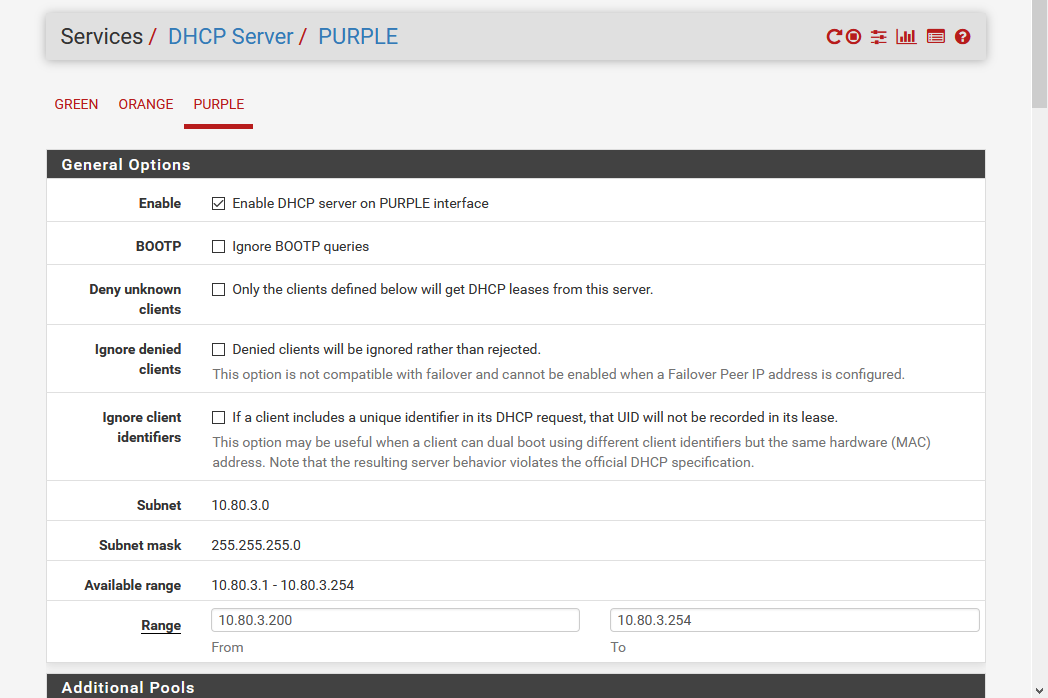
- Save
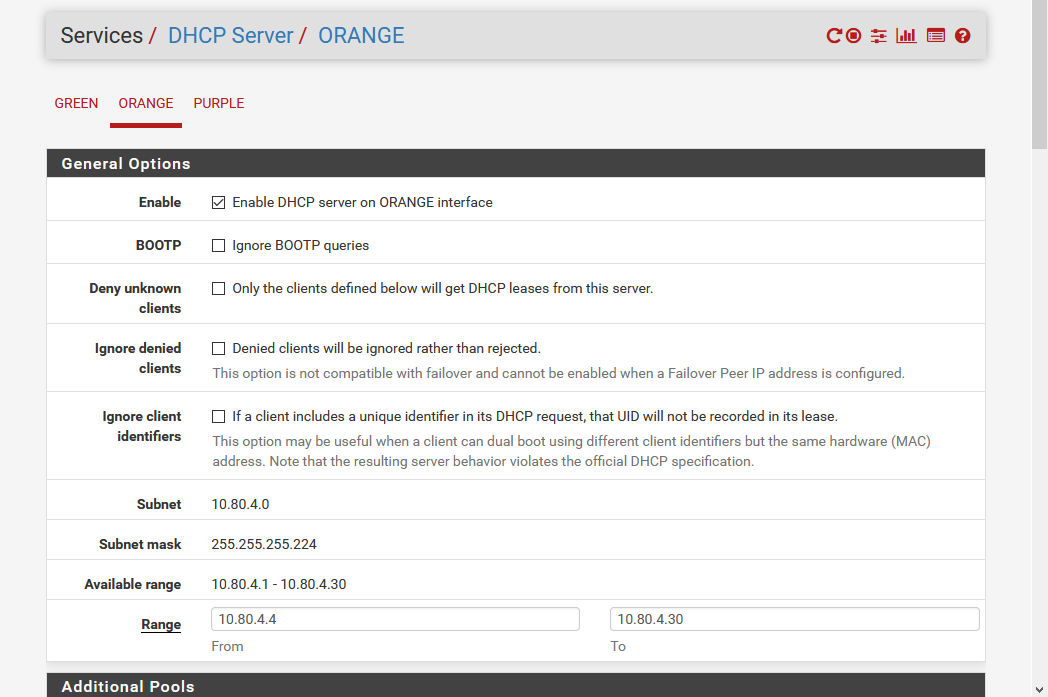
- Repeat for ORANGE adjusting the range appropriate for that subnet:
Configure Firewall Rules in pfSense
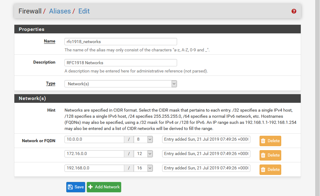
Set the rules as approrpiate to allow traffic in or out. I won’t go through this in detail except to highlight the key difference between my PURPLE and ORANGE networks is that PURPLE is permitted to access GREEN while ORANGE is not and is only able to access the Internet. This is achieved by first defining an alias called rfc1918_networks which groups together the CIDR blocks for the non-routable domains:
Then we define a rule to permit destinations that are in that not range (note the double-negative) while the final catchall rule blocks access:
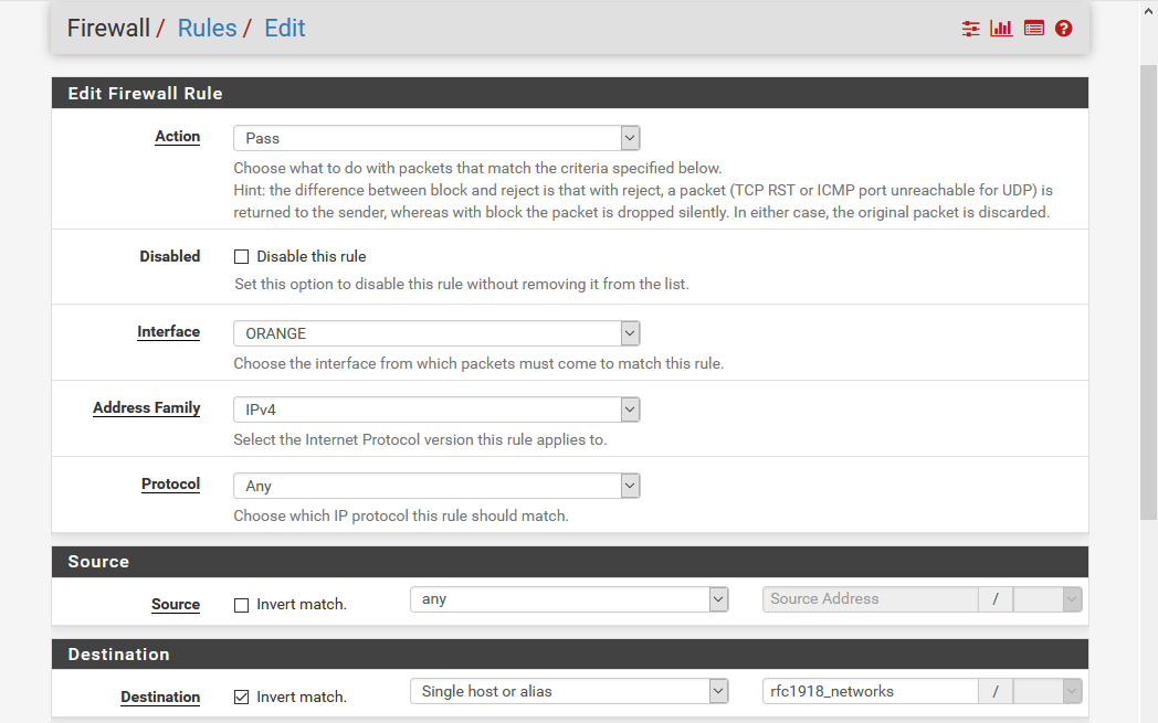
This explicitly permits ORANGE to access the Internet (non-rfc1918 addresses) while the catchall rule blocks ORANGE from accessing local addresses.
Map VLAN’s in UniFi Controller
Next we jump into UniFi Controller to map the VLAN’s to WiFi SSID’s:
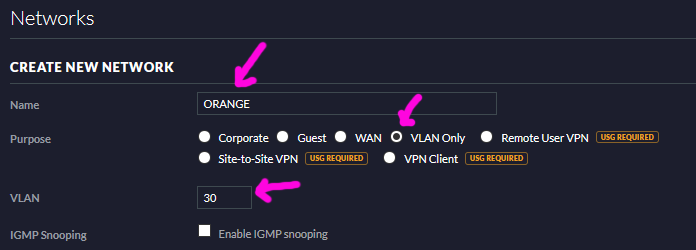
- In settings click Networks then click Create New Network.
- Select VLAN Only for purpose, name the network PURPLE and give it the VLAN tag 20 as we did in pfSense:

- Save the network then do the same thing to define the ORANGE VLAN:
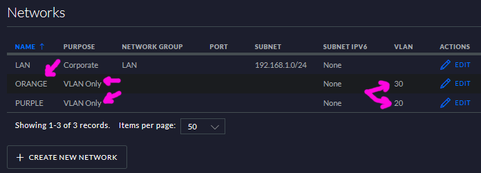
- After saving these two networks they will show in the network list - confirm they’re correct:
Define WiFi SSID’s in UniFi Controller
Next we’ll create the WiFi SSID’s and link them to our VLAN’s:
- From the Settings menu choose Wireless Networks (just above Networks) and click Create New Wireless Network
- Give the SSID name “purple” and set encryption as appropriate (e.g. WPA-PSK)
- Click Advanced Options to reveal the VLAN tag field and enter 20 so that this SSID will be handling traffic from the purple VLAN:

- Save the purple SSID and then setup the orange SSID in similar fashion:

Test
Use your phone or some other WiFi client to connect to the SSID’s - the IP address assigned should correspond to the network you connect to. For example in my case I get a 10.80.3.0/24 address when connecting to the purple SSID.
Since my UniFi nanoHD AP can host up to four SSID’s, my next step will be to define another VLAN and SSID for IoT devices such as my TP-Link smart switches so that they are even more segregated and controlled than even untrusted guest devices.